

![]()
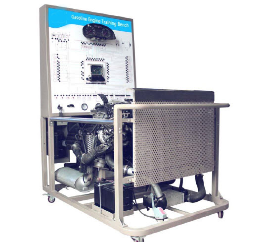
Gasoline Engine System Training Kit
เครื่องยนต์เบนซินสาธิตแบบสตาร์ท และติดเครื่องยนต์ได้
สเปคเบื้องต้น(สามารถเปลี่ยนแปลงได้ตามต้องการ)
Features
- Real and operable electronically-controlled gasoline engine to illustrate the gasoline structure and working process
- Color circuit diagram on the practical training bench is protected by 3mm-thick organic glass. The diagram and engines can help trainees learn and analyze the working principle of the control system.
- The practical training bench is installed with automobile meters, fuel meter, and vacuum pressure meter to illustrate changes of parameters including the engine speed, injection pressure and intake manifold pressure.
- Detection terminals are installed on the practical training bench. On the platform, operators can detect various detectors, executors, electrical signals of engine control unit pins, such as resistance, voltage, current, frequency, and waveform signals.
- The practical training bench is installed with diagnosis socket connecting dedicated or universal automobile decoder. The diagnosis socket reads fault codes, clears fault codes, and reads data stream from the engine electrical control system.
- A throttle controller is installed on the platform.
- A master power switch, water tank protector, flywheel protector, among other protection devices, are installed on the practical training bench.
- The practical training bench's base frame is made in steel and the surface is paint-coated. Self-retention wheels are installed to ensure that the platform is flexible, reliable and endurable.
- Intelligent fault-setting and appraisal system:
- The system employs patented, stable and anti-virus digital integrated circuit board and the latest MCU technology and associated fault setting control technology.
- Independent test and appraisal can be performed without a computer. The teacher and student interfaces are separated. Teachers enter the teacher interface to provide test paper and the students answer questions on the ordinary interface. Teachers prepare the test: teachers prepare the test: Select "Setting fault point and fault type" through the main functional menu in the MML interactive interface. Enter the password to page for setting faults. Select the set faults from the fault name list. You can select three fault types including "Open circuit fault", "Short circuit fault", and "Improper contact". Students answer questions: Enter the main menu and select "Test for skills of finding faults". After finding the fault through a test operation, students select the fault name or type. If the answer is correct, the system displays that "Correct, the fault is removed"; If the answer is incorrect, the system indicates that "incorrect, please check again". The number of attempts for each question can be set to 1-10 by the teacher. Test bank applicable to the device is integrated. The test bank can be edited according to the requirements of users.
- High resolution 3.8-inch 0.225 x 0.225 LED monitor, Chinese menu interface, friendly MML. 4 operation keys make the operation simple and quick.
- Set the line breaking, grounding short circuit and improper contact faults at any circuit. Set and control common faults relevant to module pins. Users can adjust the number and type of fault setting points.
- The RJ45 network interface is installed and the RS-232 port is provided. Use the fault setting devices of network cable or other devices to form a network to control functions including fault setting, fault removal, parameter setting, remote startup, information feedback, and appraisal through the main control computer.
Technical Parameter
- Size: 1400mm x 1000mm x 1800mm (length x width x height)
- Operating power supply: 12V DC
- Fuel No.: Engine mode
- Fuel tank size: 10L
- Operating temperature: -40℃ to +50℃
iv. Basic configuration (unit)
No. |
Name |
Specification and model |
Unit |
Quantity |
1 |
Detection control panel (protected by 3 mm-thick organic glass) |
With various detection terminals and a color circuit diagram |
Set |
1 |
2 |
A full set of meters |
|
Set |
1 |
3 |
Engineer control unit (ECU) |
|
Set |
1 |
4 |
Diagnosis socket |
|
Unit |
1 |
5 |
Ignition switch |
|
Unit |
1 |
6 |
Fuel pressure meter |
0-10 kg/cm2 |
Unit |
1 |
7 |
Vacuum pressure meter |
0-76in.Hg |
Unit |
1 |
8 |
Engine assembly |
|
Set |
1 |
9 |
Fuel tank |
10L |
Unit |
1 |
10 |
Gasoline feed pump (including the plug) |
|
Set |
1 |
11 |
Throttle controller |
|
Set |
1 |
12 |
Inlet and exhaust pipes (including protection covers) |
|
Set |
1 |
13 |
Water tank (including the stainless-steel protection cover) |
|
Set |
1 |
14 |
Cooling fan |
|
Unit |
2 |
15 |
Battery |
|
Set |
1 |
16 |
Relay |
Including: Startup, gasoline, cooling fan relays |
Set |
1 |
17 |
Fuse box |
|
Unit |
1 |
18 |
Master power switch |
50A |
Unit |
1 |
19 |
Intelligent fault-setting and appraisal system |
|
Set |
1 |
20 |
Movable framework (with self-retention wheels) |
1400mm x 1000mm x 1800mm (length x width x height) |
Set |
1 |